
- #Target not created in keil 5 install
- #Target not created in keil 5 code
- #Target not created in keil 5 plus
- #Target not created in keil 5 series
We will discuss comprehensively this startup file in the upcoming tutorials.
#Target not created in keil 5 plus
Extend the plus sign and mark the checkbox of a startup as shown in the figure below: Click on the plus sign present with the CMSIS category from the option given select CORE and mark the checkbox in front of CORE and do the same with the devices option. At this point, we only need to include two files one is the core file that is present under the category of CMSIS and the other is a startup file that is present under the category of Devices. For example, if you want to include graphics in your program you have to select it from here first.

The window for managing runtime environment is shown in the figure below:
#Target not created in keil 5 code
As I have mentioned previously that the startup files need to be included in every code so this is a portion where we will choose the inclusion of startup files. The window will then ask you to choose the runtime environment of your choice.
#Target not created in keil 5 series
we are using is TM4C123GXL but in this series you couldn’t find any board named like this. One thing to be noted down here is that the type of the microcontroller.
#Target not created in keil 5 install
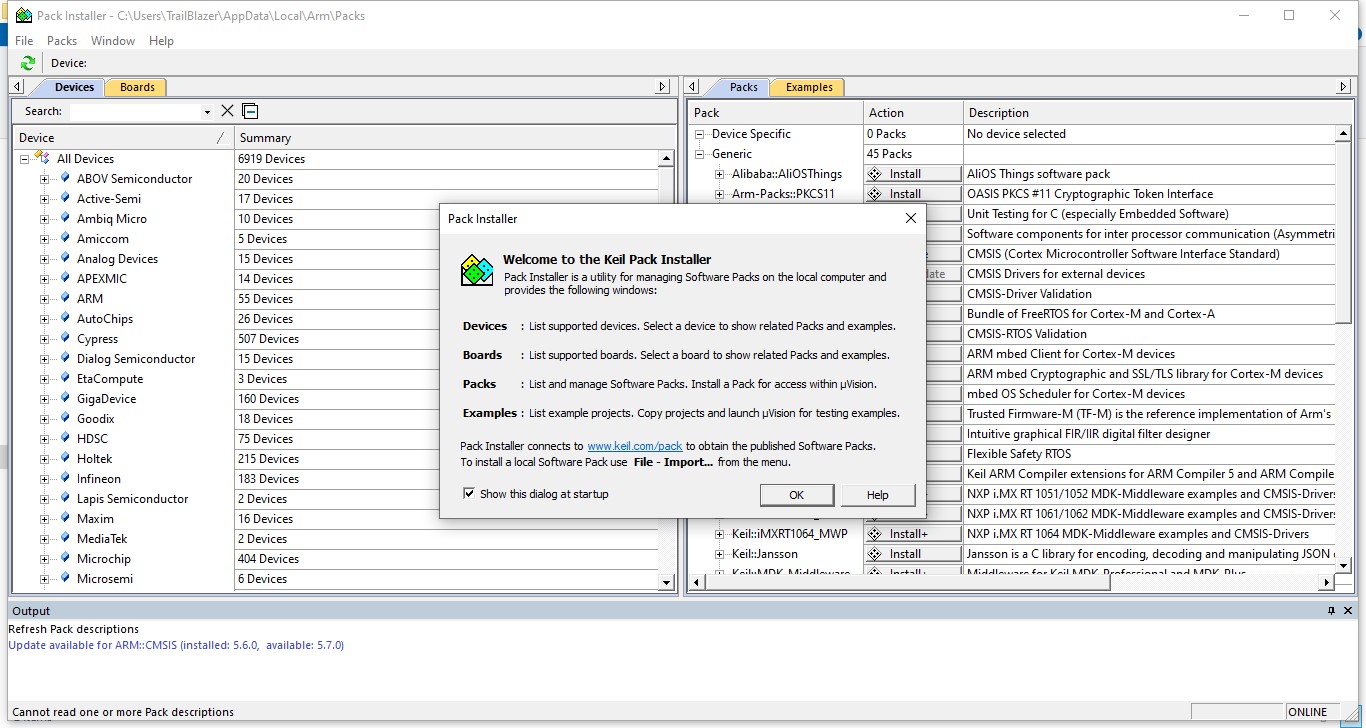
At present only two classes of TIVA C series is installed, we can install more according to our need from pack installer as we have discussed in previous tutorials, but at present, we need TM4C123x Series because our microcontroller (TM4C123G) lies within this class.As we know that TIVA c series is the only option available so we extend that too, as shown in the figure below,.When we extend this block all the downloaded board of Texas Instruments will appear as shown in the figure below, TIVA C boards are manufactured by Texas Instruments hence the board we will select at this stage is Texas Instruments. In this window two boards are present one is ARM and the other is Texas Instruments as is obvious from the above figure.

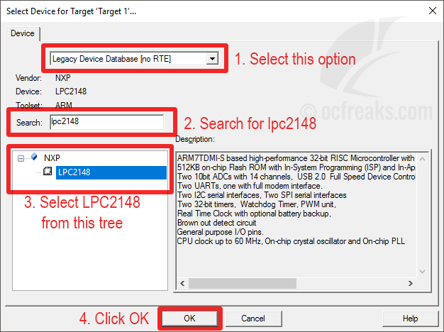
This is where we select the name and type of our board. After saving the name another window asking you to select the device with which you want to integrate this code. Hence, I named the project as a blink (In accordance with the task it is going to perform). I will use this project in the upcoming tutorial for the purpose of blinking of built in LEDs present n the F port of TIVA board. This window will ask you where you want to save the project, select the designated folder and also name you project according to the working it is going to perform in future. When you click on the New uVision Project a window will appear as shown in the figure below,.From that bar, select Project and then select New uVision Project as shown in the figure below, On the main page, as shown in the figure above, a bar is shown with file edit and view, etc. Lets’ now move to create a new project portion. If will give you a brief and concise overview of the startup files in the upcoming tutorials, you don’t have to be worried about them at this point of your understandings. To work on a program or a debugging environment we first have to create a project where will save our main and startup files. This is where all your currently open projects will appear and your main code and all the codes you run will appear in the greyed window.


 0 kommentar(er)
